GX8008C_Alexa Development Board User Guide*
- Please click the link GX8008C_Alexa Solution Software and Hardware Specifications to obtain detailed specifications
| Version | Version Update Description | Release Date |
|---|---|---|
| V1.0 | Initial Draft | 20230815 |
| V1.1 | Added serial protocol commands, Alexa cache, detailed algorithm parameters | 202301017 |
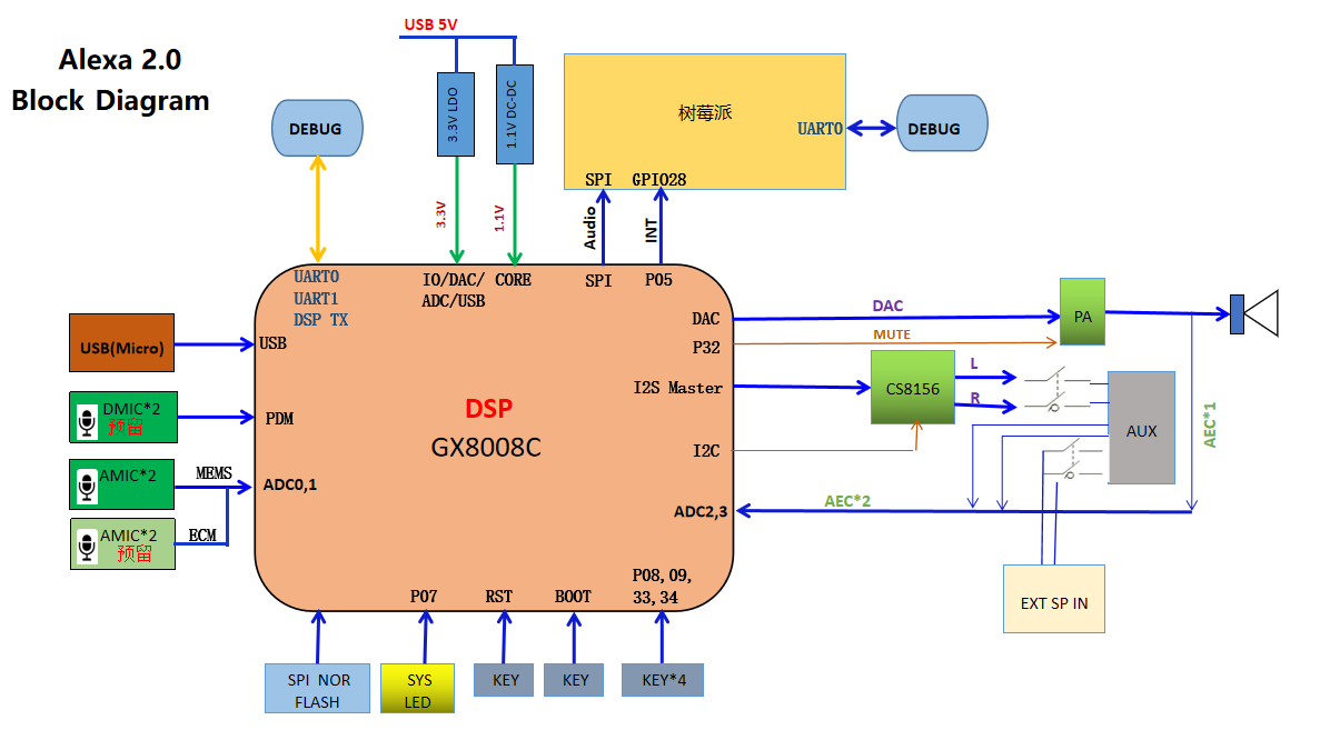
Chapter 1 NationalChip Alexa Software and Hardware Resource Introduction*
1.1 Hardware Resource Overview*
The resource diagram of the NationChip Alexa development board is shown below:
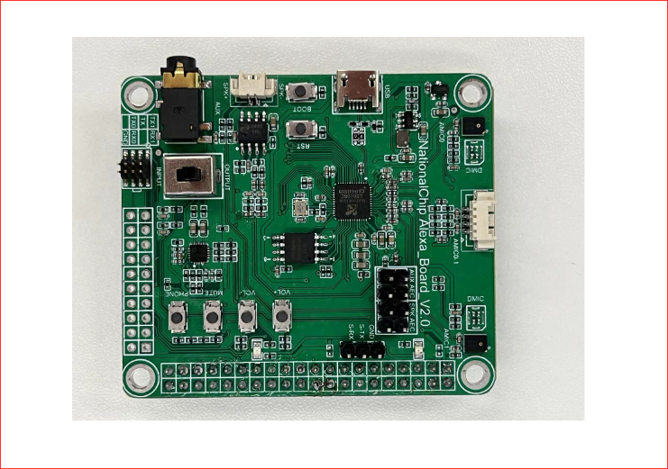
The onboard resources of the NationalChip 8008C Alexa development board are as follows:
- 1 Power indicator LED (yellow)
- 1 Status indicator LED (red)
- 1 Reset button, used to reset the 8008C
- 1 BOOT button, used for upgrading the 8008C
- 4 Function buttons (Volume+, Volume-, Mute, Phone)
- 2 Analog silicon microphones, used for sound pickup
- 1 Electret microphone interface, can connect two microphones
- 1 Mono audio output interface
- 1 USB interface
- 1 Playback control switch, used for 3.5mm audio input and output
1.2 Software Resource Overview*
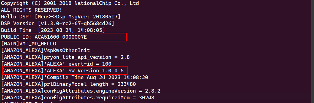
1.2.1 Viewing the Alexa Board Software Version*
Check the serial output print via the DSP_UART on the 8008C
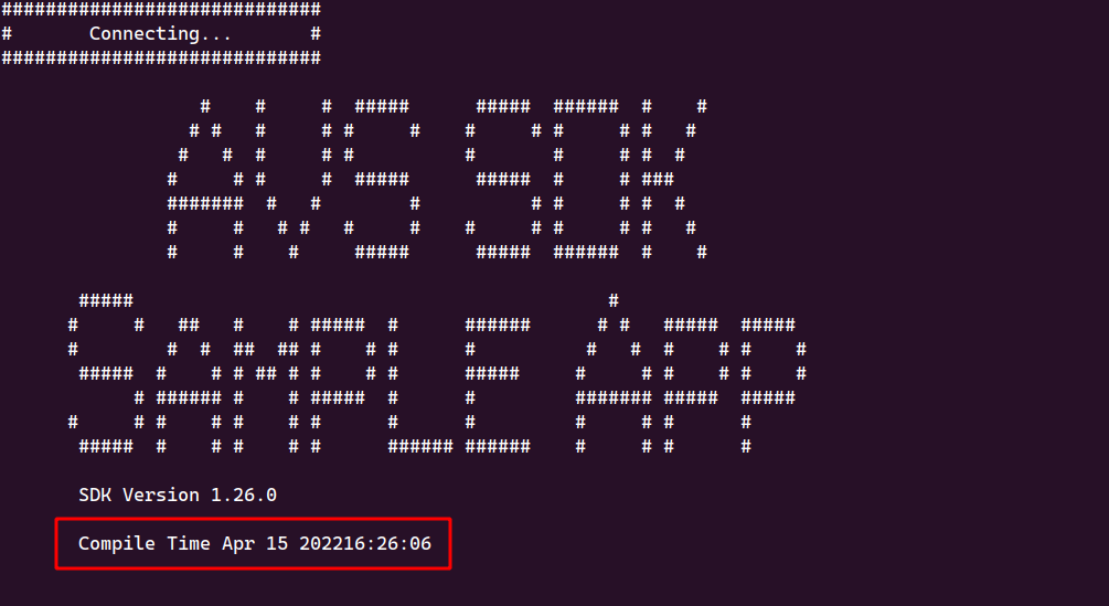
1.2.2 Viewing the Amazon AVS Version*
Chapter 2 NationalChip Alexa Solution Kit Experience*
This chapter guides users on how to use the NationalChip Alexa solution kit for development and experience.
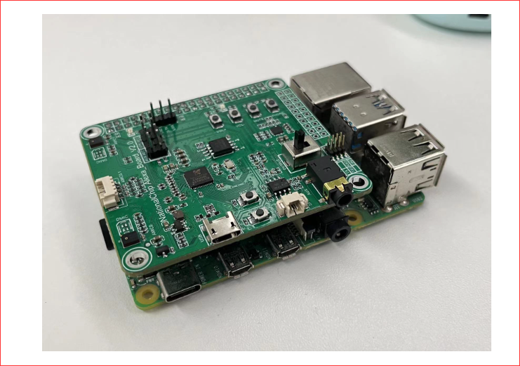
It details how to correctly combine the AVS development board and the Raspberry Pi, including connection, configuration, and development environment setup.
2.1 Alexa Kit Introduction*
-
Kit diagram, description of items inside the box
-
Alexa device, 8008C and PI
- PI Power Supply, used to power the Raspberry Pi
- Micro to HDMI adapter, used for connecting an external monitor
- 1 USB cable, used for connecting the Alexa Board to the PI
- 1 3.5mm audio cable, used for connecting speakers
- 1 3.5mm Y-splitter audio cable, used for external audio signal input
- 1 Serial port adapter board, used for Alexa Board debugging, corresponding to uart0, uart1, DSP_TX
2.2 ALEXA Kit Quick Start Experience*
- Connect the Alexa Board and the Raspberry Pi using the USB cable as shown below
- Connect the network cable to the Raspberry Pi
- Connect the Raspberry Pi power supply to power it
2.3 AVS Development Board + Raspberry Pi Usage Instructions*
2.3.1 Enabling/Disabling Auto-run AVS*
Command here
2.3.2 Connecting to Wi-Fi*
./wifi_config.sh "Wi-Fi Name" "Wi-Fi Password"
2.3.3 Running Amazon AVS*
Notes for running AVS:
-
Before running the test, ensure the account registration is successful and the network connection is established.
-
If the Raspberry Pi loses power unexpectedly, the AVS program needs to be restarted.
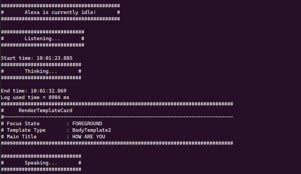
./NationalChip_8008C_Alexa_Scheme.sh
Successful execution is shown in the figure: normal testing can proceed.
2.3.4 Switching Alexa Account*
Provides steps and operating instructions for switching the Alexa account.
Ensure the Raspberry Pi is connected to the network port and the devices are correctly connected (Raspberry Pi power, 8008C -> Raspberry Pi USB port).
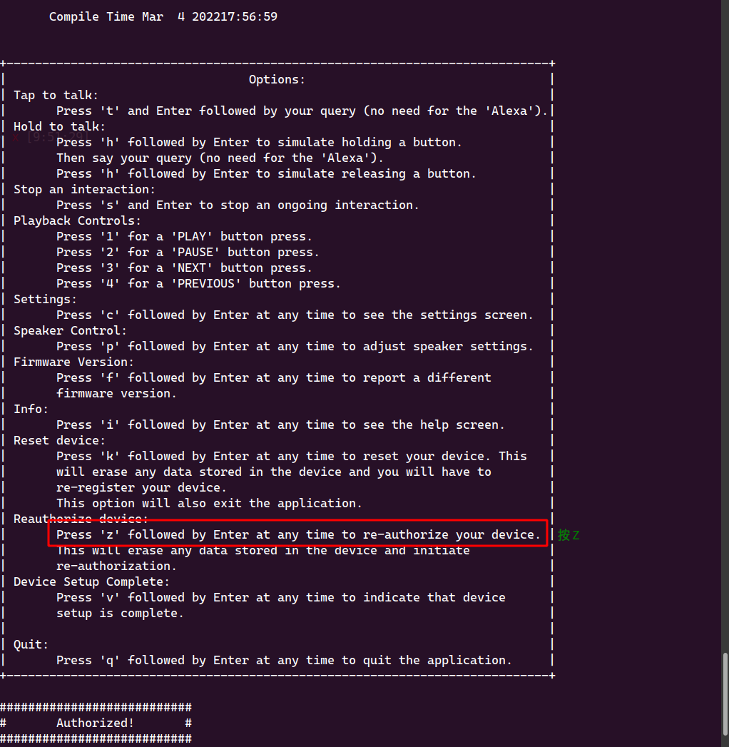
Step 1: Run the account switching program
./SwitchUserAmazonAccount.sh

Step 2: Press Z
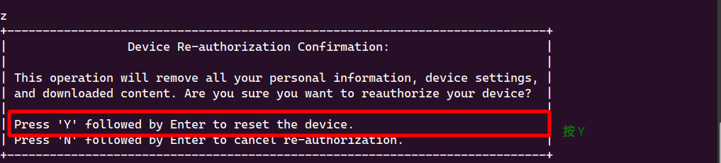
Step 3: Press Y
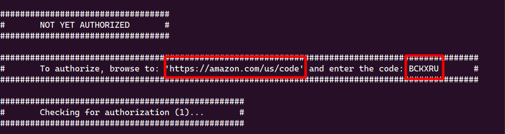
Step 4: Open the browser and go to https://amazon.com/us/code, enter the registration code, and continue with the next steps.
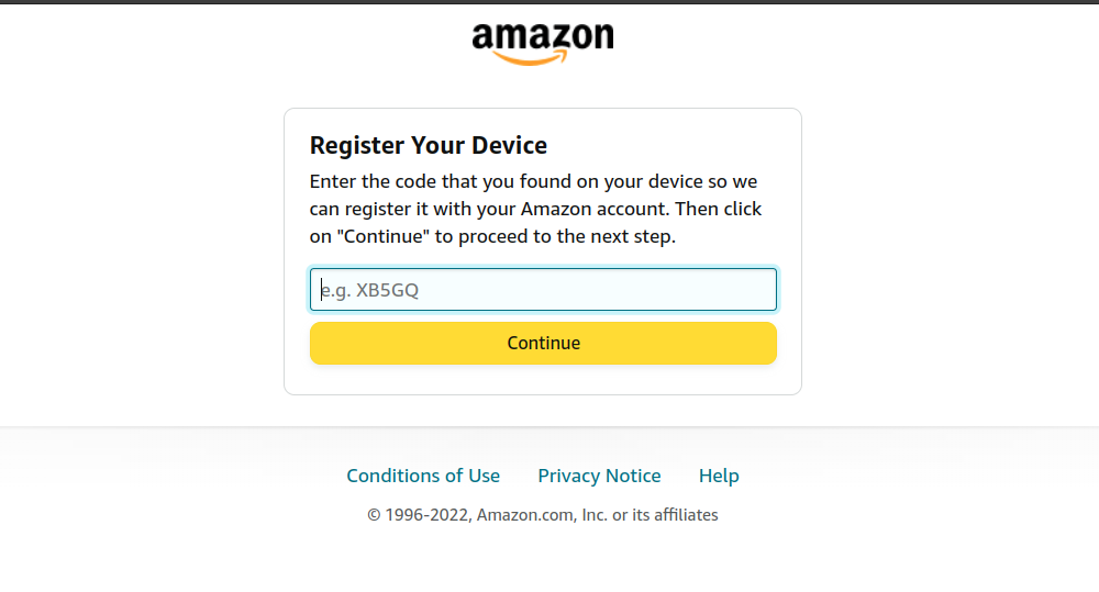
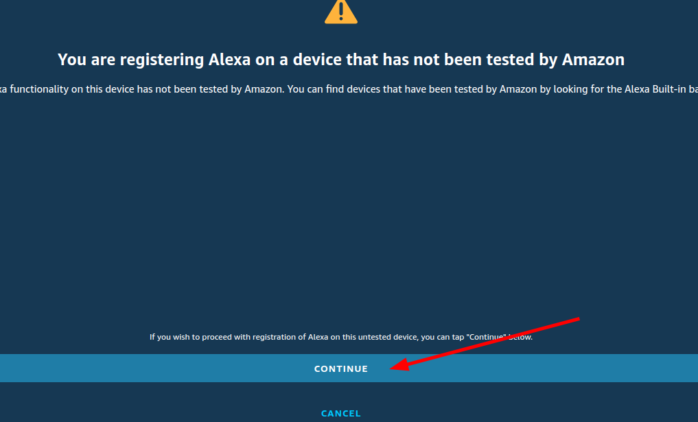
Step 5: Click Continue
Account switch successful. You will see an 8008C device under your Alexa devices.
2.4 Potential Issue Analysis Guide*
- Issue 1: When registering the Amazon device, the following print appears
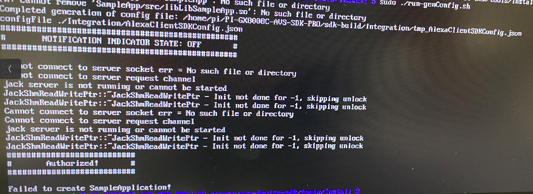
Cause: The 8008's USB is not connected to the PI_USB port of the Raspberry Pi, or there are too many USB devices connected to the Raspberry Pi.
Solution: Remove excess USB devices, reconnect the USB cable to the PI_USB port first, then reconnect other USB devices.
- Issue 2: When running the AVS test, the following print appears
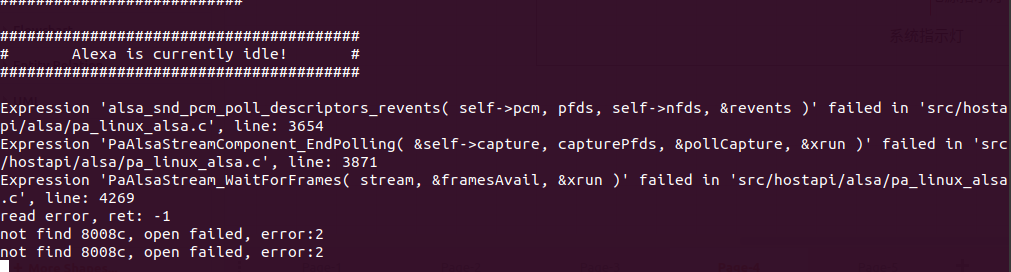
Cause: The USB cable connected to the 8008C is loose, or no USB device is inserted.
Solution: Re-plug the USB cable and secure the connection.
- Issue 3: As shown below, the wake word remains in the "Listening" state and cannot recognize speech.
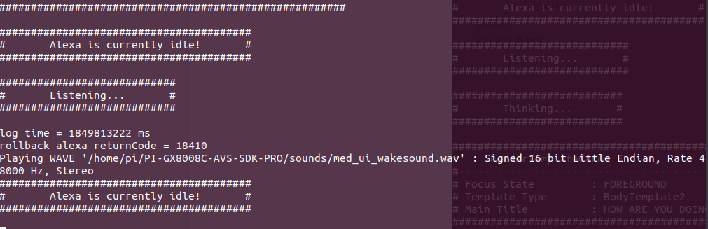
Cause: The USB cable connected to the 8008C is loose.
Solution: Re-plug the USB cable, allowing a longer interval of about 10 seconds between unplugging and plugging.
- Issue 4: During Barge-In testing, only manual adjustment of the speaker volume is supported.
- Issue 5: In case of abnormal wake-up, connect to DSP_UART to check the wake-up status.
Chapter 3 NationalChip Alexa Board 2.0 Usage*
3.1 Flashing 8008C Firmware*
- Download the flashing tool, select chip type 8008C
https://nationalchip.gitlab.io/ai_audio_docs/software/tools/NCDownloader/
3.2 OTA Upgrade*
3.2 Serial Protocol*
Port: 8008C uart0
Baud Rate: 115200
For detailed serial protocol, please refer to the Serial Protocol Guide
3.2.1 Get Version Number*
Host: 42 55 58 58 02 02 01 00 00 00 7F 61 4D 58
Slave: 42 55 58 58 02 02 00 01 08 00 25 e6 ea 29 01 00 00 01 ef 88 ff ee
Message Body Parsing
01 00 00 01 Indicates 1.0.0.1
ef 88 ff ee Indicates message body crc32
3.2.2 Talking Mode*
Host: 42 55 58 58 06 01 01 00 00 00 B9 59 7C 84
Slave: 42 55 58 58 06 02 00 01 05 00 7e da d5 07 01 1b df 05 a5
Message Body Parsing
01 (Success)
1b df 05 a5 Indicates message body crc32
3.2.3 Active (ASR) Mode*
Host: 42 55 58 58 06 02 01 00 00 00 69 23 DC C3
Slave: 42 55 58 58 06 02 00 01 05 00 7e da d5 07 01 1b df 05 a5
Message Body Parsing
01 (Success)
1b df 05 a5 Indicates message body crc32
3.2.4 Get Device Status*
Host: 42 55 58 58 0D 01 01 00 00 00 7A A9 BB EE
Slave: 42 55 58 58 0d 02 00 01 05 00 bd 2a 12 6d 01 1b df 05 a5 (Talking Mode)
Slave: 42 55 58 58 0d 02 00 01 05 00 bd 2a 12 6d 00 8d ef 02 d2 (Active Mode)
Message Body Parsing
01 Talking Mode
00 Active Mode
1b df 05 a5 Indicates message body crc32
3.2.5 Set Mic Gain (DMic 0 ~ 54)*
Host: 42 55 58 58 0B 01 01 01 05 00 15 D4 57 44 12 C5 9E BB 21
Slave: 42 55 58 58 0b 02 00 01 05 00 a0 c9 4b bb 01 1b df 05 a5 (Success)
Slave: 42 55 58 58 0b 02 00 01 05 00 a0 c9 4b bb 00 8d ef 02 d2 (Failure)
Message Body Parsing
01 (Success)
00 (Failure)
1b df 05 a5 Indicates message body crc32
3.2.6 Get Mic Gain*
Host: 42 55 58 58 0C 01 01 00 00 00 DF 7A E7 25
Slave: 42 55 58 58 0c 02 00 01 05 00 18 f9 4e a6 12 c5 9e bb 21
0x12(18) Current mic gain 18
c5 9e bb 21 Indicates message body crc32
3.2.7 Enable Factory Test Mode*
Host: 42 55 58 58 0A 01 01 00 00 00 C2 99 BE F3
Slave: 42 55 58 58 0a 01 01 01 05 00 b0 07 0b 8f 01 1b df 05 a5
Message Body Parsing
01 Indicates entering factory test mode (AEC disabled)
1b df 05 a5 Indicates message body crc32
3.2.8 Disable Factory Test Mode*
Host: 42 55 58 58 0E 01 01 00 00 00 D4 DB 2F 68
Slave: 42 55 58 58 0a 01 01 01 05 00 b0 07 0b 8f 01 1b df 05 a5
Message Body Parsing
01 Indicates entering factory test mode (AEC enabled)
1b df 05 a5 Indicates message body crc32
3.2.9. Enable Microphone*
Host: 42 55 58 58 0F 01 01 00 00 00 71 08 73 A3
Slave: 42 55 58 58 0a 01 01 01 05 00 b0 07 0b 8f 01 1b df 05 a5
Message Body Parsing
01 Enable Microphone
1b df 05 a5 Indicates message body crc32
3.2.10. Disable Microphone*
Host: 42 55 58 58 10 01 01 00 00 00 3F B8 F3 51
Slave: 42 55 58 58 0a 01 01 01 05 00 b0 07 0b 8f 01 1b df 05 a5
Message Body Parsing
01 Disable Microphone
1b df 05 a5 Indicates message body crc32
3.2.11. Send Alexa Index*
Slave: 42 55 58 58 11 01 09 01 14 00 17 fe 77 70 80 d9 6e 46 00 00 00 00 80 06 6f 46 00 00 00 00 1e 91 fe 42
Message Body Parsing
startIndexInSamples :80 d9 6e 46 00 00 00 00 -> Decimal: 1181669760
endIndexInSamples:80 06 6f 46 00 00 00 00 -> Decimal: 1181681280
1e 91 fe 42 Indicates message body crc32
3.2.12 Algorithm Parameters*
AGC Parameters (Parameter Range 0 ~ 25)*
Read AGC Parameters*
-
Magic Number:
0x42 0x55 0x58 0x58 -
Message
Command Attribute B_CHECK Message Body Length Message Body Content Host 0x09 0x01 0 0 None Slave 0x09 0x01 0x01 (8-byte Data + 4-byte crc) AGC -
Read AGC Parameters
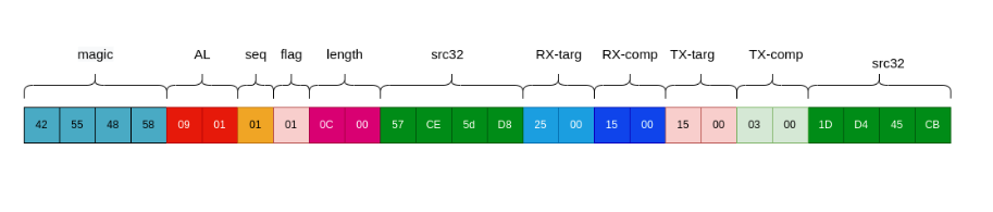
Host: 42 55 58 58 09 01 01 00 00 00 6C EB 2A 75 Slave: 42 55 58 58 09 01 01 01 0c 00 57 ce 5d d8 25 00 15 00 15 00 03 00 1d d4 45 cb -
Slave Read Data Example Diagram
Slave Parameter Parsing
The message body content contains 8 bytes (AGC data) + 4 bytes (32-bit CRC checksum)
The AGC parameters mainly include TargetLevelDbfs and CompressionGaindB
- TargetLevelDbfs: Target Level, in decibels relative to full scale (dBFS). It defines the target level value for the desired output audio signal. AGC will attempt to automatically adjust the gain of the input audio signal to approach or reach the target level. A higher target level will result in the output audio signal being closer to the maximum level, while a lower target level will result in the output audio signal being closer to the minimum level. Note: This is equivalent to adjusting the maximum amplitude of the output audio.
- CompressionGaindB: Compression Gain, in decibels (dB). It represents the gain value applied to the input audio signal before AGC compression is applied. Compression gain is used to control the dynamic range of the input audio signal and affects the audibility of the output audio signal. A higher compression gain will result in more compression of the input audio signal's dynamic range, while a lower compression gain will result in less dynamic range compression.
As shown in the RX-targ, RX-comp, TX-targ, TX-comp fields in the message body in the figure above.
0x25 0x00 (RX-targ) : Indicates the target level for the receive-side audio signal.
0x15 0x00 (RX-comp) : Indicates the compression gain for the receive-side audio signal.
0x15 0x00 (TX-targ) : Indicates the target level for the transmit-side audio signal.
0x03 0x00 (TX-comp) : Indicates the compression gain for the transmit-side audio signal.
0x1D 0xD4 0x45 0xCB : Indicates the crc32 checksum of the message body.
Set AGC Parameters*
-
Write AGC Data Example
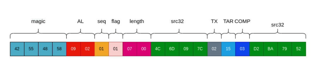
Example 1, TX Data Host: 42 55 58 58 09 02 01 01 07 00 4C 6D 09 7C 02 15 03 D2 BA 79 52 Slave: 42 55 58 58 0b 02 00 01 05 00 a0 c9 4b bb 01 1b df 05 a5 (Success) Example 2, RX Data Host: 42 55 58 58 09 02 01 01 07 00 4C 6D 09 7C 01 25 15 29 87 AD 7B Slave: 42 55 58 58 0b 02 00 01 05 00 a0 c9 4b bb 01 1b df 05 a5 (Success) -
Message Structure Example Diagram:
Host Message Body Parsing
0x01(TX) / 0x02(RX) : Setting for a specific audio signal. TX indicates the transmit-side audio signal, RX indicates the receive-side audio signal.
0x15(TAR) : TargetLevelDbfs: Target Level
0x03(COMP) : CompressionGaindB: Compression Gain
AEC Parameters (Parameter Range 0 ~ 10)*
Read AEC Data*
-
Read AEC Parameters
Host: 42 55 58 58 08 01 01 00 00 00 C9 38 76 BE Slave: 42 55 58 58 08 01 01 01 08 00 f6 d8 6d 77 04 00 00 00 4b 48 26 ae -
Slave Read Data Example Diagram
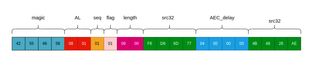
Message Body Parsing
AEC_delay is the delay time introduced during the echo cancellation process. It represents the time difference between the audio signal being played through the speaker and the reflected echo being received by the microphone. By measuring this time difference, the algorithm can determine the appropriate phase and gain compensation to eliminate the echo.
0x04 0x00 0x00 0x00(AEC_delay) : Delay time 4ms.
0x4B 0x48 0x26 0xAE :Indicates the crc32 checksum of the message body.
Set AEC Data*
-
Write AEC Data Example
Host: 42 55 58 58 08 02 01 01 05 00 6B DC 63 85 03 37 BE 0B 4B Slave: 42 55 58 58 0b 02 00 01 05 00 a0 c9 4b bb 01 1b df 05 a5 (Success) -
Message Structure Example Diagram:
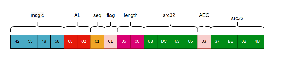
Message Body Parsing
0x03 : Set delay time to 3ms.
0x37 0xBE 0x0B 0x4B : Indicates the crc32 checksum of the message body.
EQ Parameters (Parameter Range -20 ~ 20)*
Read EQ Data*
The host sends a command to read EQ parameters, and the slave returns the EQ parameter data for both RX (receive side) and TX (transmit side) at once.
Host: 42 55 58 58 07 01 01 00 00 00 1C 8A 20 4F
Slave: 42 55 58 58 07 01 00 01 94 00 50 c8 73 e3
RX-BandFre    :   3e 00 00 00(62)  7d 00 00 00(125)  09 01 00 00(265)  20 03 00 00(800)  e8 03 00 00(1000)     c4 09 00 00(2500)   a0 0f 00 00(4000)  88 13 00 00(5000) 40 1f 00 00(8000)
RX-bandGain:  00 00 00 00(0)  00 00 00 00(0)  00 00 00 00(0)  03 00 00 00(3)  00 00 00 00(0)
      00 00 00 00(0)  00 00 00 00(0)  00 00 00 00(0)  00 00 00 00(0)

TX-BandFre    :   3e 00 00 00(62) 7d 00 00 00(125) a0 00 00 00(160) ee 02 00 00(750) e8 03 00 00(1000)        d0 07 00 00(2000) a0 0f 00 00(4000) 88 13 00 00(5000) 40 1f 00 00(8000)
TX-bandGain:  00 00 00 00(0) fc ff ff ff(-4) fc ff ff ff(-4) fc ff ff ff(-4)  00 00 00 00(0)
        00 00 00 00(0) 00 00 00 00(0)  00 00 00 00(0)  00 00 00 00(0)
Crc32:        :   57 d2 79 2e
Slave Message Body Parsing:
The message body contains 144 bytes (Data) + 4 bytes (32-bit CRC). Every 4 bytes represents one parameter.
EQ has two parameters: EqBandFre (center frequency in Hz) and EqBandGaindB (band gain).
RX (far-end) audio signal EQ data:
0x3e 0x00 0x00 0x00 (RX-BandFre-1) : Indicates the receive-side frequency of 62 Hz.
0x7d 0x00 0x00 0x00 (RX-BandFre-2) : Indicates the receive-side frequency of 125 Hz.
...
0x40 0x1f 0x00 0x00(RX-BandFre-9) : Indicates the receive-side frequency of 8 kHz. Note: Maximum is 8k.
0x00 0x00 0x00 0x00 (RX-bandGain-1) : Indicates the band gain for the receive side at the RX-BandFre-1 (62Hz) frequency is 0 dBA.
0x00 0x00 0x00 0x00 (RX-bandGain-2) : Indicates the band gain for the receive side at the RX-BandFre-2 (125Hz) frequency is 0 dBA.
...
0x00 0x00 0x00 0x00 (RX-bandGain-9) : Indicates the band gain for the receive side at the RX-BandFre-9 (8kHz) frequency is 0 dBA.
TX (near-end) audio signal EQ data:
0x3e 0x00 0x00 0x00 (TX-BandFre-1) : Indicates the transmit-side frequency of 62 Hz.
0x7d 0x00 0x00 0x00 (TX-BandFre-2) : Indicates the transmit-side frequency of 125 Hz.
...
0x40 0x1f 0x00 0x00(TX-BandFre-9) : Indicates the transmit-side frequency of 8 kHz. Note: Maximum is 8k.
0x00 0x00 0x00 0x00 (TX-bandGain-1) : Indicates the band gain for the transmit side at the TX-BandFre-1 (62Hz) frequency is 0 dBA.
0xFC 0xFF 0xFF 0xFF (TX-bandGain-2) : Indicates the band gain for the transmit side at the TX-BandFre-2 (125Hz) frequency is -4 dBA.
...
0x00 0x00 0x00 0x00 (TX-bandGain-9) : Indicates the band gain for the transmit side at the TX-BandFre-9 (8kHz) frequency is 0 dBA.
The data parsing is as follows.
RxEqBandFre          = {62, 125, 250, 800, 1000, 2000, 4000, 5000, 8000},
RxEqBandGaindB       = { 0,   0,   0,   3,     0,    0,    0,    0,    0},
TxEqBandFre          = {62, 125, 160, 750, 1000, 2000, 4000, 5000, 8000},
TxEqBandGaindB       = { 0,  -4,  -4,  -4,     0,    0,    0,    0,    0},
Write EQ Parameters*
-
Write EQ Data Example
Host: 42 55 58 58 07 02 01 01 4D 00 B3 AB 95 4C RX: 01 BandFre: 3e 00 00 00(62) 7d 00 00 00 (125)a0 00 00 00 (160) ee 02 00 00 (750)e8 03 00 00(1000) d0 07 00 00(2000) a0 0f 00 00(4000) 88 13 00 00(5000) 40 1f 00 00 (8000) bandGain: 00 00 00 00 (0)00 00 00 00(0) 00 00 00 00 (0)03 00 00 00 (3)00 00 00 00 (0)00 00 00 00 (0)00 00 00 00(0) 00 00 00 00 (0)00 00 00 00 (0) Crc32: : 12 4E b0 09 Slave: 42 55 58 58 0b 02 00 01 05 00 a0 c9 4b bb 01 1b df 05 a5 (Success) Host: 42 55 58 58 07 02 01 01 4D 00 B3 AB 95 4C TX: 02 BandFre: 3e 00 00 00(62) 7d 00 00 00 (125)a0 00 00 00 (160) ee 02 00 00 (750)e8 03 00 00(1000) d0 07 00 00(2000) a0 0f 00 00(4000) 88 13 00 00(5000) 40 1f 00 00 (8000) bandGain: 00 00 00 00 (0)00 00 00 00(0) 00 00 00 00 (0)03 00 00 00 (3)00 00 00 00 (0)00 00 00 00 (0)00 00 00 00(0) 00 00 00 00 (0)00 00 00 00 (0) Crc32: : 41 AC 95 CA Slave: 42 55 58 58 0b 02 00 01 05 00 a0 c9 4b bb 01 1b df 05 a5 (Success) -
Host Message Body Parsing
1-byte flag + 72 bytes (Data) + 4 bytes (crc32)
0x01(TX) / 0x02(RX) : Setting for a specific audio signal. TX indicates the transmit-side audio signal, RX indicates the receive-side audio signal.
RX receive-side audio signal EQ data:
0x3e 0x00 0x00 0x00 (RX-BandFre-1) : Indicates the receive-side frequency of 62 Hz.
0x7d 0x00 0x00 0x00 (RX-BandFre-2) : Indicates the receive-side frequency of 125 Hz.
...
Content as per EQ Read Parameters.
3.4 Alexa Rollback*
The shared memory ring buffer meets the requirement for transmitting continuous utterances to AVS, including 500ms of pre-roll, the wake word, and the user's request for cloud-based wake word verification. This reduces latency and the need for multiple copies of audio samples. Official documentation: https://developer.amazon.com/en-US/docs/alexa/alexa-voice-service/implement-ww-verification.html .
The following diagram illustrates one approach; other implementations are permitted as long as the necessary functionality is maintained:
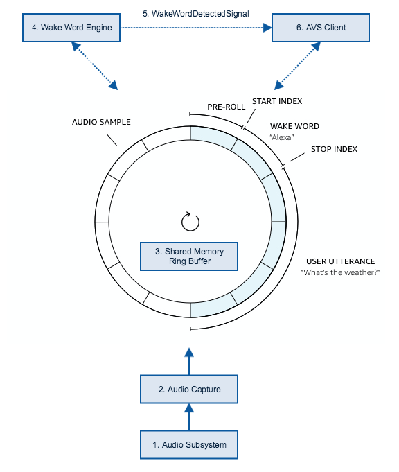
Method 1: AVS Client-side Implementation
Click to download: AVS Client Rollback Method.zip
Method 2: The 8008C caches the Alexa audio and sends it to the AVS Client via UART or SPI.
Click to download: serial_cache_tool.zip
The length of one frame of data is 4-byte header + 960 bytes of voice data, totaling 38 frames.
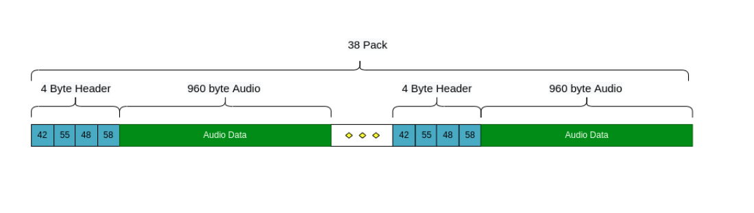
3.4.1 Connection Diagram*
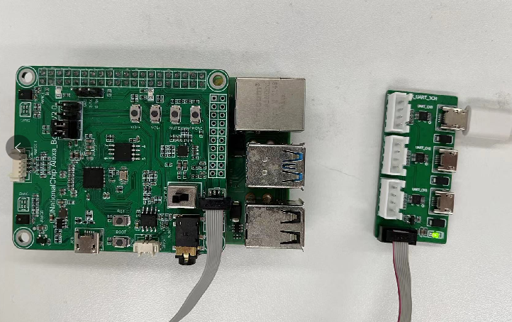
3.4.2 Receiver Function Verification*
Step 1: Compile the code
cd serial_cache_tool
make linux
Step 2: Run the receiver program
sudo ./serialDemo.elf /dev/ttyUSB0 # Modify according to the recognized USB device
Say the wake word "Alexa", and the data should be received normally as shown below.

Use Audacity to import alexa.pcm
3.5 Analyzing Algorithm Output Audio*
Step 1: Install Audacity*
https://www.audacityteam.org/download/windows/
Installation steps: Omitted
Step 2: Connect the 8008C to the PC*
Step 3: Open Audacity, select the sound card*
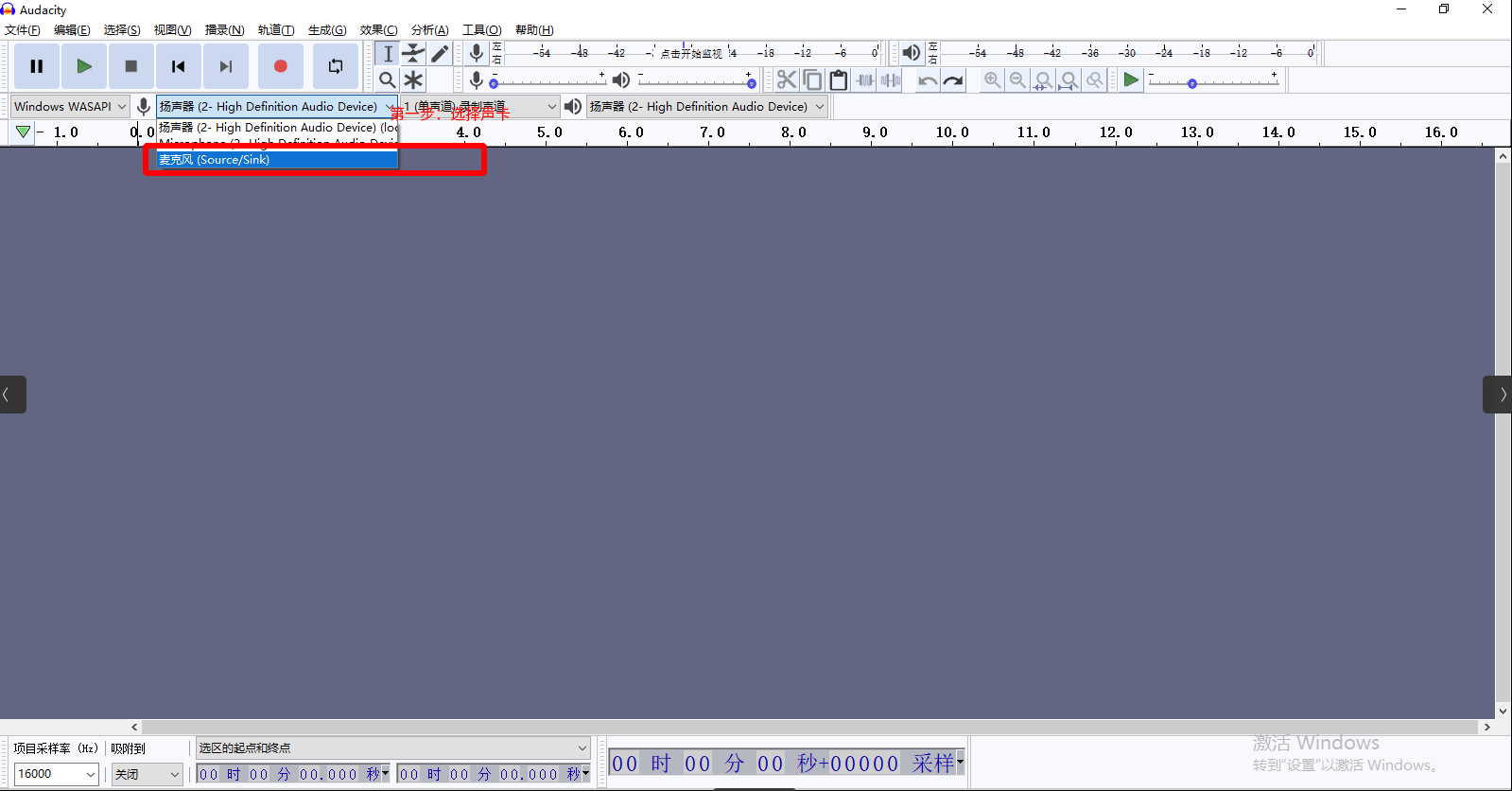
Step 4: Record audio*
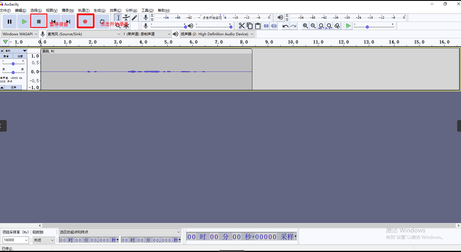
Potential Issues*
- No data on the channel when recording on Windows.
Solution: Open Device Manager, right-click on the Nationalchip Conference Speaker sound card (Uninstall device), then re-plug the USB cable.
3.6 Microphone Consistency, Speech Level Output Fixed Volume*
Chapter 4 Alexa Standard Testing*
-
Our internal kit needs to complete the Alexa test standard and output test data.
-
Customer machine testing also needs to complete the Alexa test standard and output a report. After testing, the customer will have their own account. We need to switch to our account and complete the Alexa testing.
Acoustic Structure Testing*
Test items for the mic, including quiet background noise, self-playback self-recording, and gain adjustments.
Self-Playback Self-Recording*
-
Play white noise
-
Point 1: Use Amazon calibrated white noise. Max 3M-----------------------65dBa----to mic 82dBA
AFE Testing*
《Alexa Far Field Reference Solutions Acoustic Qualification Test User Guide V2_2.pdf》
《OSL_verification_AN-AVS-0084 .pdf》
《TR-001_AcousticReport_NationalChip_AFE_FT.docx》
《NationalChip_AFE_FT_RefSol_Scoresheet_External_V2.2.xlsx》
《Wake_up_latency_self_test_checklist_nationalchip_AFE.xlsx》