Overview*
This document briefly introduces the SDK acquisition steps and development environment setup for the GX8006 WiFi voice large model solution, helping you get started quickly.
1. Obtaining the SDK*
Register GitLab
The SDK for the GX8006 WiFi voice large model solution is deployed on our GitLab server. Developers need to register before pulling the relevant code for secondary development. For the registration tutorial, refer to Register GitLab
After registration and approval, you will see the following two SDKs under the group Voice WiFi Solution:
- lighting: Large model solution SDK developed based on the LN882H WiFi chip
- ovp_aiot: Large model solution SDK developed based on the GX8006 voice chip
2. Setting Up the Development Environment*
2.1. Setting Up the ovp_aiot Development Environment*
For details on setting up the ovp_aiot development environment, see GX8006 SDK Development Environment Setup
2.2. Setting Up the lighting Development Environment*
Note
The current SDK only maintains the CMake + GCC build method. The Keil project files in the SDK are reserved for the LN882H SDK and do not support direct compilation. If you need to use Keil to build the project, you must refer to the CMakeLists.txt under project to add the relevant source code to your project.
2.2.1 Related Software Description*
- Python3: Python scripts are used in the build, and the SDK path must not contain Chinese characters. Python2 is not supported.
- ARM GCC Toolchain: Use the official ARM GNU Arm Embedded Toolchain: version 10-2020-q4-major
- CMake: Generates the corresponding Makefile or build.ninja file based on the selected generator. Recommended version >= 3.16
- Ninja: Build tool that processes the build.ninja file generated by CMake
- Make: Reads the Makefile generated by CMake and invokes the compiler suite to generate targets
- SEGGER JLink: Optional, used for flashing firmware and can also start a GDB debug server. Recommended to install V752d or lower versions
- LN882H Serial Flash Tool: Optional, used for flashing firmware via the serial port. For related information, refer to LN882H Document Collection
- Visual Studio Code: Optional
Tip
Install the above software as needed.
2.2.2. Installation Instructions Based on Ubuntu 20.04 x64*
- Use the package manager to install the necessary dependency software
sudo apt install python3 cmake ninja-build make
- Install the cross-compilation toolchain
- Click the link to download gcc-arm-none-eabi-10-2020-q4-major-x86_64-linux.tar.bz2
- Extract the toolchain:
sudo tar -xf gcc-arm-none-eabi-10-2020-q4-major-x86_64-linux.tar.bz2 -C /opt - Configure the environment variable
export CROSS_TOOLCHAIN_ROOT=/opt/gcc-armnone-eabi-10-2020-q4-major. You can add this to a custom script or./.bashrc; otherwise, you need to configure this environment variable every time you open a new shell.
- SEGGER JLink (Optional)
- Click the link to download v7.52d 64-bit DEB Installer
- Install:
sudo dpkg -i JLink_Linux_V752d_x86_64.deb
2.2.3. Debug Environment Setup Instructions Based on VSCode+GDB*
- Complete the above Installation Based on Ubuntu 20.04 x64
- Install VSCode and the following plugins yourself
- C/C++ IntelliSense
- CMake
- CMake Tools
- Cortex-Debug
- Connect the JLink debugger to the PC and test whether the debugger is connected:
(base) zhuhy@zhuhy-lenovo:~$ lsusb Bus 002 Device 001: ID 1d6b:0003 Linux Foundation 3.0 root hub Bus 001 Device 002: ID 1366:0101 SEGGER J-Link PLUS Bus 001 Device 001: ID 1d6b:0002 Linux Foundation 2.0 root hub - Open the
CMakeLists.txtin the SDK root directory, find the following section, and change the build type to Debug# set(CMAKE_BUILD_TYPE Release CACHE STRING "build for release" FORCE) set(CMAKE_BUILD_TYPE Debug CACHE STRING "build for debug" FORCE) - Recompile and flash the firmware under build-ln_model_public-debug to the LN882H
- Create a new
.vscode/launch.jsonwith the following content, whereserverpathshould be modified to the JLink installation path andarmToolchainPathto the toolchain installation path{ // Use IntelliSense to learn about related attributes. // Hover to view descriptions of existing attributes. // For more information, visit: https://go.microsoft.com/fwlink/?linkid=830387 "version": "0.2.0", "configurations": [ { "name": "Cortex Debug", "type": "cortex-debug", "cwd": "${workspaceFolder}", "executable": "${workspaceFolder}/build-ln_model_public-debug/bin/ln_model_public.elf", "request": "attach", "runToEntryPoint": "main", "showDevDebugOutput": "both", "servertype": "jlink", "serverpath": "/usr/bin/JLinkGDBServerCLExe", "device": "Cortex-M4", "interface": "swd", "armToolchainPath": "/opt/gcc-arm-none-eabi-10-2020-q4-major/bin" } ] } - Start debugging to perform single-step debugging in the VSCode UI.
3. Development Guide*
3.1. ovp_aiot Development Guide*
Under Development
3.2. lighting Development Guide*
3.2.1. Framework Introduction*
The WiFi voice large model development solution is located in project/ln_model_public
This solution mainly consists of three major parts:
First, cloud integration, i.e., bidirectional audio interaction with the cloud, as well as the transmission of some control messages.
Second, interaction with the GX8006 voice chip, i.e., serial-based bidirectional audio transmission and flow control, and the sending of related control commands, such as configuring playback parameters, setting volume, etc.
Third, based on Xiaozhi Cloud, a complete set of authorization and OTA examples, as well as an example of implementing control based on MCP, is provided.
3.3.2. Cloud Integration*
The source code for cloud integration is located in app/servers
- Cloud integration abstracts an interface
app/servers/server_interface.h. Integrating with different clouds requires implementing the function definitions of this interface. - The interaction with the cloud is abstracted as:
- Connection and disconnection, along with corresponding connected callbacks
- Audio upload, i.e., receiving user voice data passed from other modules in the application layer, packaging it into the format specified by the cloud, and pushing it to the cloud
- Audio download, i.e., implementing the download of cloud TTS and other data, and passing it to other modules in the application layer through callback functions
- Transmission of related control information, such as audio start/stop messages, wake word information, MCP control messages, etc.
3.3.3. Serial Port Integration with GX8006*
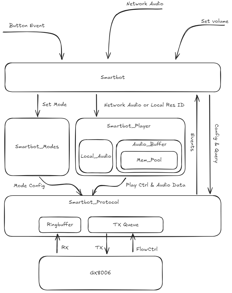
The source code for serial port integration is located in app/smartbot
- The module extracts two interfaces to the lower layer, namely one for receiving and one for sending; this part is relatively fixed. If porting is needed, please refer to the Serial Protocol Porting Guide
smartbot_on_outputis used to register the serial send function. The module internally calls this function to output byte streams to the serial port.smartbot_proto_inputis used to pass in the serial received byte stream. The module internally parses the data frames.
Note
This interface briefly disables interrupts to copy data to the ringbuffer, but the subsequent protocol parsing behavior is performed in the thread context.
- The module extracts two playback interfaces to the application layer, used for playing local audio and cloud audio, respectively.
- Local audio is stored in the Flash code section. Only the corresponding ID is provided during playback, and this module automatically pushes the corresponding audio.
- Cloud audio is buffered in the RAM area. During playback, the cloud module passes data into this buffer, and this module automatically handles the serial interaction with the GX8006.
- Local playback has higher priority than cloud playback
- The overall framework diagram of this module is as follows:
3.2.4. Authorization Management*
Tip
Currently using Xiaozhi's authorization management as an example. Different clouds should implement according to the actual situation.
The authorization management of this solution has two steps
- Step 1:
- At the factory, send a POST request to the authorization server with its own unique identifier
- Parse the returned data and extract the encryption key and unique identifier
- Write the key to the local OTP or a special Flash area
- Step 2:
- After the user starts the device, check whether it has a valid key; otherwise, do not execute subsequent application code
- Send a POST request to the server with challenge information encrypted by the key, and the server determines whether authorization is granted
- If the device is new and has not been bound, the server returns a binding verification code, and the user can bind the device by opening the console
- If the device is already bound, the cloud returns the MQTT connection parameters for interaction, and the device can establish interaction with the cloud after connecting
3.2.5. OTA*
Since this solution includes two chips, the OTA part is divided into two parts: the GX8006 part and the LN882H part
In this OTA solution, the LN882H acts as the host and leads the upgrade work of both chips
3.2.5.1. GX8006*
GX8006 OTA implements bare-chip upgrade through the serial port connected to the LN882H, i.e., the same principle as flashing firmware via the serial port using a PC host tool during development. This solution implements HTTP-based streaming OTA.
The OTA source code is located in project/ln_model_public/app/ota, and the GX8006 bare-chip upgrade protocol implementation is located in project/ln_model_public/modules/gx_fornax_boot.
For the specific bare-chip upgrade process, refer to the Serial Bare-Metal Upgrade Reference Example
3.2.5.2. LN882H*
Under Development
3.2.6. MCP*
Xiaozhi's MCP implementation is located in project/ln_model_public/app/servers/xiaozhi/mcp.c. Currently, tools for getting device status information and setting volume have been added.
It supports configurable independent thread execution. By setting call_in_task to true, a thread is automatically created to execute the relevant function when the large model calls this tool.
Users can create custom tools as needed and, combined with appropriate prompts, implement control requirements based on the large model.
static mcp_tool_t mcp_tools[] = {
    {
        .name = "self.get_device_status",
        .description =
            "Provides the real-time information of the device, including the current status of the audio speaker, screen, battery, network, etc.\n"
            "Use this tool for: \n"
            "1. Answering questions about current condition (e.g. what is the current volume of the audio speaker?)\n"
            "2. As the first step to control the device (e.g. turn up / down the volume of the audio speaker, etc.)",
        .call = mcp_tool_handle_get_device_status,
        .call_in_task = false
    },
    {
        .name = "self.audio_speaker.set_volume",
        .description =
            "Set the volume of the audio speaker. If the current volume is unknown, you must call `self.get_device_status` tool first and then call this tool.",
        .call = mcp_tool_handle_set_volume,
        .call_in_task = false,
        .properties = {
            {
                .name = "volume",
                .type = kPropertyTypeInteger,
                .has_min_value = true,
                .min_value = 0,
                .has_max_value = true,
                .max_value = 100
            }
        }
    },
    {
        .name = NULL
    }
};